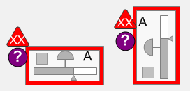
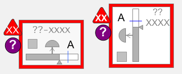
Most valves appear in several versions, which differ in the amount of information shown surrounding the valve. The different versions correspond roughly to the types of display pages they are typically expected to be used on.
Alarm borders are re-sized as needed for the different versions.
Level 3 valves are the baseline version for every valve. They contain all of the information elements available. All of the examples described above show Level 3 valves. These objects are expected to be used heavily on detailed operating graphics (“Level 3” operating graphics) where showing a full complement of information is most important.
Level 2 valves are expected to be used on “Level 2” operating graphics, which provide overviews of major areas or units. Level 2 valves are identical to their Level 3 counterparts with the exception that the visibility of some of the elements can be “switched off” (i.e., hidden from view) by operators (during run time). The intent is to allow operators some flexibility in the amount of detail shown on their Level 2 operating graphics.
Note: Whether this feature is implemented using visibility properties for a single object or by creating separate objects is at the discretion of the implementation team.
The “Show/Hide Settings” controls are used by the operator to select which elements are shown for Level 2 valves. The intent is to provide this functionality globally on a workstation via a button on the toolbar and/or via a right click menu.
Elements which can be (independently) hidden are:
All of the other common elements for valves remain unchanged.
For Level 2 valves the visibility of the numeric OP will be forced on if the valve goes into an alarm state.
Level 1 valves can be used on the overview displays covering an operators entire span of control (“Level 1” operating graphics). These displays tend to focus more on visual presentation of process status, and less on details. Level 1 objects therefore have the visibility of tagnames/nicknames and the numeric OP elements set to “off”. Unlike Level 2 valves, these elements cannot be re-enabled by operators using the Show/Hide Settings selections.
On Level 1 valves, the visibility of the numeric OP will be forced on if the valve goes into an alarm state.
All of the other common elements for valves remain unchanged.
Basic valves provide page designers with a small-footprint option for special situations requiring only a basic set of information for a given valve. Basic valves do not show the tagname/nickname field, or the numeric OP and units (if applicable). Basic valves can be vertical or horizontal. Basic valves can also be mirrored in either orientation.
Basic valves with tags are identical to basic valves except that they retain space for a tagname/nickname field. This makes the footprint slightly larger. Basic (with tag) valves can be vertical or horizontal as shown below. They can also be mirrored in either orientation.
Note All valve versions should include orientation options as per the individual object specifications.
Published June 2018