This defines the name of the Citect SCADA server with which the I/O device will communicate. See Add an I/O Server Process.
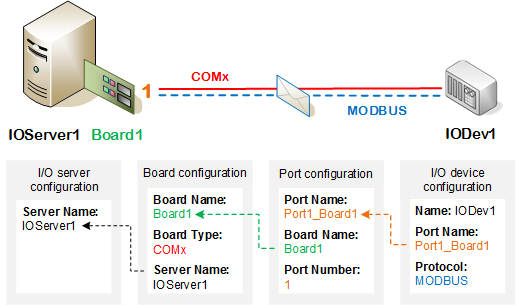
Setting up communications between a device and a Citect SCADA I/O server typically involves the following steps:
This defines the name of the Citect SCADA server with which the I/O device will communicate. See Add an I/O Server Process.
This defines which board on your I/O server computer to use (for example, the mother board, network card, serial board or a PLC communication card). See Add a Board.
Often boards have multiple communication ports and you need to specify the port to use. Some equipment can have several logical (virtual) ports assigned to the one physical port. See Add a Port.
This defines the I/O device in Citect SCADA and specifies its address. The protocol is also defined at this level. See Add an I/O Device.
The following diagram shows how the elements in the configuration environment map to the software components in the runtime system.

An I/O device driver is also required to implement the protocol and transport. Citect SCADA supports over 140 device drivers, enabling communication with a vast array of production devices across several communication types. These include generic drivers that support industry-standard protocols such as OPC and Modbus. Much of the functionality of the protocols and transports can be modified using the driver options and parameters. See Working With Device Drivers.
A good place to start when setting up communications is with the Device Communications Wizard, a tool that automatically configures a default setup according to your specified requirements. Once you understand how the setup works, you can manually configure arrangements that are more complex.
Note: If there is no data to read or write, Citect SCADA will not communicate with an I/O device regardless of whether it is defined or not. You need to create a variable tag and use it before Citect SCADA will do a read request. For example, use an integer variable to display a number on a page.
Published June 2018