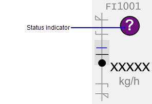
Status indicators are used to represent various non-alarm conditions associated with an object, such as abnormal data quality or control system states. A status indicator will only appear while the triggering condition is true.

The status indicator is a separate genie and is used to represent various states of an object.
The status indicator symbols can be found in the SA_Library project in a library called sa_status_indicator.
Connects to: EquipmentName.EqStatus
A status indicator can represent the following states.
|
Symbol |
State |
Name |
|---|---|---|
|
|
Bad data. |
d2 |
|
|
Uncertain data or invalid automation state. |
d1 |
|
|
Simulate mode - forcing a value to a point. |
d4 |
|
|
Offscale. |
d12 |
|
|
Interlocked. |
d6 |
|
|
Interlock bypassed. |
d5 |
|
|
Paused. |
d19 |
|
|
Bad Communication between IO Server and Client | d13 |
|
|
Tracking | d20 |

|
Clamped | d21 |
|
|
Off-spec lab data. |
d7 |
|
|
Maintenance. |
d8 |
|
|
Message. |
d9 |
|
|
Restart of the machine is required. |
d11 |
|
|
Initialization manual or index car. |
d3 |
|
|
Timer is active. Flashes when close to finishing. |
d10 |
|
|
Calibrate mode. Used to calibrate instruments. |
d16 |
|
|
Bad Communication between Gateway and PLC. | d14 |

|
Deviation | d15 |

|
Reminder to call outside personnel | d17 |
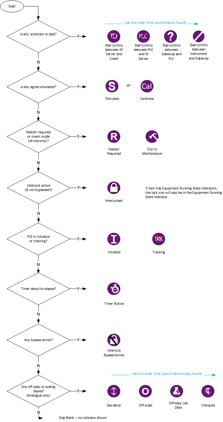
In scenarios where several states may be active at the same time there is an order of precedence on what indicator will be displayed. For example, a PID controller that is in initialize mode, but also has the PV as simulated would display the "S" indicator, even if there was also an interlock condition active.
The following diagram outlines the order of precedence:

Status Indicators can be configured for most library objects excluding NumericInput and TextInput. Examples have been provided for Drives, Meters and Valves only.
Status Indicators can be used to highlight a non-alarm state of an object or equipment. You can configure equipment to use status indicators one of two ways:

The SA_Style_1_MultiRes starter project includes an example (Indicators.ci) of how to configure equipment using sample functions to call one of the indicators. Variations of the equipment status indicator functions have been provided for Meters, Valves and Drives only.
These functions map the relevant status tags from a PLC's code into the values required by the various indicators. Different pieces of equipment have different relevant states for each of these indicators, so when required, make your own copy of the example cicode file. You can then create variations or unique versions of the sample functions to use in your project.
Refer to the comments within the cicode file Indicators.ci for more information on how to customize and use these functions.
See also
Published June 2018