This example illustrates how tags are used to achieve interaction with faceplates.
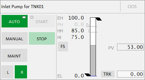
The CtrlModeDef tag sets the default mode of operation for a piece of equipment. If you set this tag to 0 for a pump, the default mode of a pump will be Auto. That is indicated on the faceplate by a rectangle in the top-right corner of the Auto button on the faceplate as shown below.

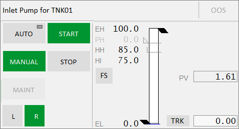
The CtrlMode tag represents the current mode for a piece of equipment. If the CtrlModeDef (default) and CrtlMode (current) have different values, the current mode will be displayed in green. For example, the CtrlModeDef = 0 (Auto) and the CtrlMode = 1 (Manual), the Manual button will be displayed in green. Clicking the Manual button will set the ManCmd tag to 1.

If the pump is not running, the Start button will also be displayed in green to allow you to manually start the pump. If the pump is running, the Stop button will be green allowing you to manually stop the pump. The Auto button will continue to display the rectangle to indicate that it is the default mode. Note that the Start and Stop buttons are available only when the mode is Manual.
Note: Clicking any button will set its <name>Cmd tag to 1. For example, clicking the Manual button will set ManCmd to 1.

When you click one of the buttons, a circle will appear in the top-left corner to indicate that a command (Start in the above image) has been sent to the PLC mapped to the corresponding tags. Once the Start command is completed, the circle will disappear as the PLC sets StartCmd to 0 (or StopCmd to 0 in case you clicked the Stop button). In addition, the PLC sets the value of the Running tag to 1 (Stopped tag if you clicked the Stop button). When you click Stop, the value of the Stopped tag is 1.