The Analog Indicator faceplate can be associated with regular meters such as an Analyzer meter.
The Analog Indicator faceplate comprises the following components:
| Component | Description | Associated Tags |
|---|---|---|
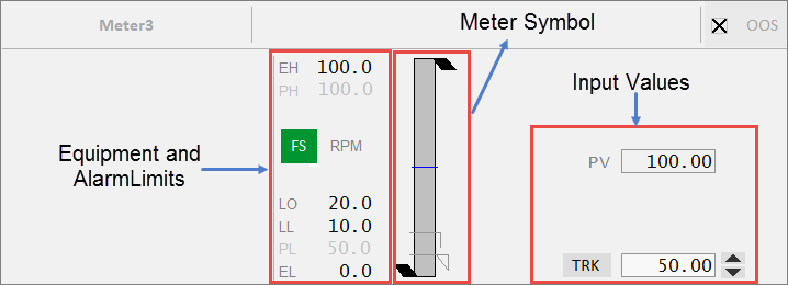
| Equipment Limits |
The following limits are displayed for this faceplate:
If the values lie outside the practical values, additional indicators are displayed. The color of the equipment limits changes as the meter values change. If the practical range is the same as the engineering range, the practical range will be hidden. |
|
| Alarm Limits |
Displays the following alarm limits:
These are the standard analog alarm limits. If these alarm limits are not configured, they will not be displayed. Note: You can now configure custom digital alarm limits based on the PLC alarm limits. The FS (Full scale) button can be used to toggle the meter into full scale even when the PV is within the practical range. The units of measurement of the PV are displayed to the right of the FS button. |
Note: These tags are used if the UsePLCLimits parameter is "true" unless the PLCLimits parameter has been changed from the default. If UsePLCLimitsParameter is "false", values come from the alarm limit configuration of the PV tag. |
| Faceplate Inputs |
Shown on the right hand side. Most of these are selected in the Composite Genie presentation options. These include:
|
Published June 2018