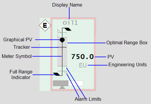
The figure below shows an example of the elements that make up a meter.

Graphical PV connects to: EquipmentName.PV, EquipmentName.PVTarget
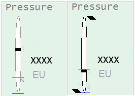
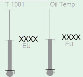
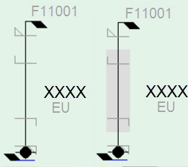
The appearance of the meter symbol and graphical PV tells operators what type of reading is being displayed (flow vs. temperature vs. pressure, etc.). For example, flow meters are represented as a basic ‘stick’ shape, with a black dot as the graphical PV. Temperature meters resemble a thermometer. Level meters resemble a (thin) vessel with a fill that rises and falls to represent the level, and so on. The symbols and PVs for each type of meter are shown in the following image.
|
Analyzer Meter |
Deviation Meter |
Flow Meter |
Level Meter |
Misc Meter |
Pressure Meter |
Target Meter |
Temperature Meter |

|

|

|

|

|

|

|

|
Connects to: EquipmentName.PRHigh, EquipmentName.PRLow, EquipmentName.PR
Each meter allows you to set a “normal” operating range ( “practical” range). During most operating situations, the meter’s full range is much bigger than the actual region of interest. By setting the normal operating range you can see meaningful variation in the PV when looking at the meter.
The EquipmentName.PR item is applicable to Deviation meters only. PRHigh and PRLow are not applicable to these meters.
If the PV moves outside the normal operating range, the meter scale will automatically change to show the full range of the instrument. To differentiate a meter that is showing its full range, additional flags appear at the top of the meter and the meter symbol line color changes from grey to black, as in the example below:

Connects to: EquipmentName.PV (analog alarm - current) or (EquipmentName.HHAlm, EquipmentName.HAlm, EquipmentName.LAlm, EquipmentName.LLAlm) or PLC Alarm Limits if configured.
The alarm limit indicators appear on the meter symbol to show the location of any configured alarm limits. This allows operators to see when a PV is approaching an alarm limit. Four types of alarm limits are shown using different symbols.
Note: For more information about configuring PLC alarm limits, see Associate PLC Limits with Equipment.

|
High high alarm limit |

|
High alarm limit |

|
Low alarm limit |

|
Low Low alarm limit |
For more information, see Alarm Indicators.
An alarm limit indicator will not appear if the corresponding alarm limit is not configured for the instrument or if the limit is outside of the range shown by the meter. Note that the precise width of the alarm limit indicators varies somewhat for different meter types in order to accommodate the width of the meter symbol. For example, alarm limit indicators are wider on a level meter than on a flow meter.
Connects to: EquipmentName.PV (eng units field).
The engineering units represent the unit of measurement for the instrument.
Connects to: EquipmentName.PV, EquipmentName.PVTarget
The numeric PV provides a text-based representation of the instrument reading. This provides operators with precise values when needed.
The display name/nickname shows the instrument name (by default), or, if entered by the user, a “display name”. The nickname is usually a common name used to help identify the reading (e.g., “Oil temp”, instead of “TI1001”). The field accommodates up to 79 characters.

Connects to: EquipmentName.ORHigh, EquipmentName.ORLow, Visibility connected to EquipmentName.ORDsp.
The optimal range box highlights a specific range of the meter. Typically, operators will use this feature to remind themselves of the desired or “optimal” range for the PV, depending on the operating conditions. It should be possible to enable and set the endpoints for the optimal range from the point detail. If the optimal range is not set or enabled, the box is not shown.

Connects to: EquipmentName.PVTrack, EquipmentName.OPTrack, EquipmentName.TrackDsp.
Similar to the optimal range box, the tracker is a user-configured indicator that marks a specific value on the meter. An operator can mark the current value of a PV so that when they look at the reading again later, they can see if it has changed. The tracker can be set and enabled/disabled from the meter faceplate.
![]()
See Also
Published June 2018