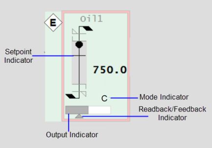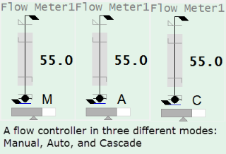
When a meter is used to show readings from a controller, additional information is included. Control meters include all of the common elements previously described for regular meters, plus the additional elements shown below.

Connects to: EquipmentName.SP
The setpoint indicator is an additional mark on the meter symbol (similar to the tracker and alarm limit indicators) which shows the position of the controller setpoint value.
Connects to: EquipmentName.OP
The outer rectangle shape with white fill represents the entire range of the controller output (typically 0-100%), while the darker fill represents the output value.
Connects to: EquipmentName.FB
This small triangular indicator represents the actual output for the controller (if available from the control system). It shares the same scale as the controller output indicator (e.g. 0-100%). This allows the operator to quickly see if the output and actual output values match. This can be particularly useful where the controller has a ramping function.
Connects to: EquipmentName.CtrlMode, EquipmentName.CtrlModeDef
This is a single-character code that indicates the mode of the controller. Typically, the set of modes includes Manual (M), Auto (A), and Cascade (C).

Control Mode Indicator states:
Note: The Mode Indicator is not displayed if the tag is set to CtrlModeDef. To view the control mode at all times, remove the CtrlModeDef tag from the equipment template.
See Also
Published June 2018