Variable tags allow you to reference a specific I/O device variable.
To add a variable tag:
For a description of the properties, see below.
To successfully configure a variable, you need to complete the Tag Name, I/O Device, Addressand Data Type fields. All other fields are optional.
Variable Tags Properties
Note: If a variable tag was generated by the Equipment Editor, a number of fields on the properties form will be shaded. To configure these fields, you will need to use Equipment Editor (see Using Equipment Editor to Generate Tags).
Property |
Description |
---|---|
Equipment |
The name of the equipment associated with the variable tag. Select a name from the drop-down list of existing equipment definitions, or enter a name. There is a limit of 254 characters across the Equipment and Item Name fields, including any separating periods (.). |
Item Name |
The name of the item with which the variable tag is associated. Items form part of an equipment hierarchy. They can be used to associate tags, alarms and trends with a particular attribute of a physical piece of equipment (see Items). There is a limit of 254 characters across the Equipment and Item Name, including any separating periods (.). Note: When entering an Item Name, there are a number of reserved words that you need to avoid. These reserved words relate to syntax that is used for tag extensions. They are: |
|
UNINTENDED EQUIPMENT OPERATION Do not mix the use of odd and even variable addresses as boundaries when you are concatenating registers. Failure to follow these instructions can result in death, serious injury, or equipment damage. |
Field |
Description |
---|---|
Tag Name |
You can use any name for a tag (79 characters) provided it follows the tag name syntax rules and isn't the same as the name of a Cicode function within the project or any included projects (see Tag Name Reserved Words for a list of restrictions on naming). If you have many tags, use a naming convention (see Using Structured Tag Names). This makes it easier to find and debug your tags. When the tag name is referenced on a graphics page, Cicode, etc., it can be used with or without a specific tag element or item. If you are using distributed serversIf your plant consists several sections or systems, you can assign a cluster to each individual section, and then monitor all sections using one control client. Don't use distributed servers to split up a single section or process into discrete areas. A single cluster system with distributed processing would be better used here since it would not be hampered by the maintenance overhead of a distributed server system (such as extra project compilations, and so on)., the name needs to be unique to the cluster (for example, you cannot have the same variable tag name in more than one cluster). Note: Citect SCADA will automatically resolve tags without a cluster context specified if every tag name in the project is unique. See Clusters. |
Cluster Name |
The name of the cluster that runs the variable tag. This field needs to be defined if your project has more than one cluster. You can leave this field blank in a multi-cluster system if cluster replication is enabled (see the parameter |
I/O Device |
The name of the I/O device where the variable is stored (31 characters). If using I/O device redundancy, you need to specify the primary I/O device name here, not the standby. Note: Avoid changing the tag's I/O device name from this FORM as the variable.dbf will not be updated. If you do change the tag's I/O device name you will need to clear the tag's reference fields. |
Data Type |
The type of I/O device variable (16 characters). I/O devices support several data types that are used to exchange data with Citect SCADA. Because of the lack of an industry standard, many I/O device manufacturers use individual naming conventions for their I/O device variables. However, every variable corresponds to one of the tag data types. Note: If you do not specify a range for your tag, then an out of range alert message will be generated if you write a value which is outside the range of the type. You need to specify the correct data type that corresponds to the data type of the I/O device variable you are configuring. Each data type has a unique address format. You need to use this format when you are specifying the address of the variable (as the Address property). You will want to verify that you only use data types that are valid for your I/O device. If you do not specify a data type, the variable will be treated as 16-bit integer. Citect SCADA supports concatenation of I/O device registers. For example, you can define a real data type (in Citect SCADA) as two contiguous int data types (in the I/O device). Citect SCADA reads across the boundary of the two INTs and returns a REAL. If you use concatenation of registers, the address of the variables needs to be on odd boundaries or even boundaries. You cannot mix address boundaries. For example, V1, V3, V5 are valid addresses. Be careful when using this feature: the I/O device needs to maintain the integrity of the second register. (If the I/O device writes to the second int, the value of the real could be corrupted.) The structure of some I/O devices might not support this feature, and might therefore behave unpredictably. |
Address |
The register address in the I/O device where the variable is stored (254 characters). The format and prefix of an address will depend on the protocol configured for the I/O device, which can be determined by checking the Protocol field on the I/O devices view in Citect Studio. |
Comment |
Any useful comment (254 characters). |
Deadband |
(11 characters). A deadband allows the value of a variable tag to fluctuate within a defined threshold without updates being sent through the system. This may be useful if a tag produces many small, insignificant value changes. The threshold is represented as a percentage of the tag's engineering range. The default value is 0 (zero), which captures every value change. For example, if a variable tag has an engineering range of zero to 10000, a deadband of 1 would mean a change in value would have to be greater than 100 (or 1 percent of the range) to be recognized. If the current value was 5600, the tag in the PLC would have to change to a value greater than 5700 or less than 5500 before an update would be sent through the system. The deadband setting for a variable tag will not apply to an associated trend tag. If a trend tag requires a deadband setting, it should be configured independently in the trend tag properties. |
Eng Units |
(8 characters.) The engineering units that the value represents (for example %, deg, mm/sec, etc.). This property is optional. If you do not specify engineering units, no engineering units are used. |
Format |
(11 characters). The display format of the value (of the variable) when it is displayed on a graphics page, written to a file, or passed to a function (that expects a string). This property is optional. If you do not specify a format, the format defaults to ####.##. For more information, see Format Specifiers. |
Field |
Description |
---|---|
Raw Zero Scale / Raw Full Scale |
The unscaled (raw) values (of the variable) that represent the zero point and full scale point for the data (11 characters). The raw values are the values that Citect SCADA reads from the I/O device. |
Eng Zero Scale / Eng Full Scale |
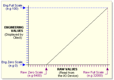
The scaled values that Citect SCADA calculates from the raw values (11 characters). The Raw Zero Scale is scaled to the Eng Zero Scale and the Raw Full Scale is scaled to the Eng Full Scale. These properties are represented in engineering units and are used as the upper and lower limits of trends and bar graphs. Many I/O devices return an integer to indicate the value of an analog input. To return a usable value, the I/O device converts an input signal (usually 4-20 mA) to a raw scale variable, usually in the range 6400 to 32000. To present this variable as a meaningful value, you can specify a scaling calculation. Citect SCADA then scales every value accordingly, as in the following diagram.
The scaled value of the variable (engineering value), not its raw value, is used throughout the system. The scaling properties are optional. If you do not specify scaling, Eng Zero Scale defaults to Raw Zero Scale, and Eng Full Scale defaults to Raw Full Scale; that is, no scaling occurs. A value that is below the specified Raw Zero Scale or above the specified Raw Full Scale causes an "Out of Range" alert message in your runtime system. |
Field |
Description |
---|---|
Custom 1 to Custom 8 |
A user-defined string can be used for storage of static information. Information contained within custom1...8 can be used for categorization purposes, as such, it does not usually change during runtime. |
Field |
Description |
---|---|
Historize |
This field enables you to automatically historizeAn object ID associated with every tag in a project that uniquely identifies the tag for use by tag-based drivers, automatically generated at compile. It is used instead of the actual address of the register (which is what most other drivers use to read from and write to I/O devices). and publish the specified variable tag in Schneider Electric's Historian application. If you set this field to "TRUE", the variable will be included in an automated configuration process within the Historian environment. If you set the field to "FALSE" (or leave it blank), the variable will not be included. |
Property |
Description |
---|---|
Project |
The project in which the variable tag is configured. |
See Also
Published June 2018