System Projects Reference > Situational Awareness System Projects > Situational Awareness Library Project > Complex Valve

Complex Valve

The Complex Valve faceplate can be associated with the Block Valve.

Note: To use for other valve types, create a copy of the faceplate and update the valve type in the composite genie.

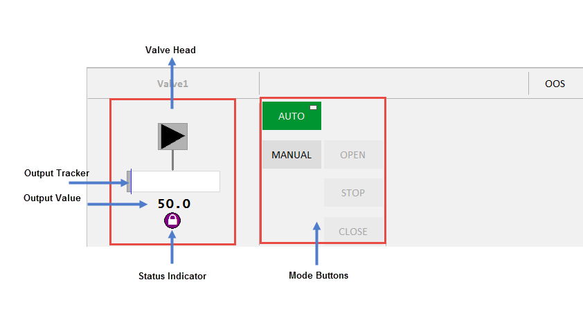
The Complex Valve faceplate comprises the following components:

Component

Description

Associated Tags

Valve Head

Valve Symbol associated with the selected equipment.


Mode buttons

Auto, Manual, Open, Close and Stop buttons are displayed on this faceplate. The button is green when a mode is active. When the tag associated with the equipment is 0, the mode is Auto. When the tag is 1, the mode is Manual.

The Control Mode button displays two symbols:

  • The circle in the top-left corner indicates that a command has been sent to the linked PLC. This indicator is not visible otherwise.
  • The rectangle in the top-right corner indicates that the current mode is the normal mode of operation for the equipment. Displayed on the Auto/Manual buttons, the rectangle depends on ‘CtrlModeDef’
 
  • Auto: Automatic mode
 
  • Manual: Manual mode
 
  • Open: Open mode - This is a toggle button that toggles the "OpenCmd". The Open button is active (green) when ‘OpenCmd’ tag is 1. The button is disabled when the valve is in AUTO mode or the valve has an interlock/shutdown condition preventing the valve from being operated.
  • OpenCmd
 
  • Close: Close mode - This is a toggle button that toggles the "CloseCmd". The Close button is active (green) when ‘Closedmd’ tag is 1.The button is disabled when the valve is in AUTO mode or the valve has an interlock/shutdown condition preventing the valve from being closed.
  • CloseCmd
 
  • Stop: Stop mode - This is a toggle button that toggles the .The Stop button is active (green )when ‘Stopped’ is 1. The button shall be disabled when the valve is in AUTO mode.
  • StopCmd

Mode Indicators

Local, Manual, Auto and Cascade Mode.

Local - Local Mode – field or MCC control only.
Manual - Manual Mode - start/stop or valve position set by control room operator
Auto Mode - start/stop and valve position set by control system, control operator sets Setpoint target.
Cascade mode – control system sets setpoint target from another loop/logic.

Equipment Status Indicator Displays if there is an abnormal status condition e.g. bad comms (stop IO server).
Output Tracker Blue line on output bar. The position of the output tracker is based on the ‘OPTrack’ tag and visible when ‘TrackDsp’ tag is 1.
Output Value Number below the output bar . This uses the ‘OP’ tag which is the same for the output bar. The units of the OP will be displayed to the right of the number if configured .


Published June 2018