The Valve objects that are available in the Situational Awareness library include:
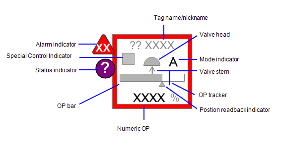
The figure below shows an example of the elements that may make up a control valve object.

An alarm indicator is used to show the occurrence and status of alarms associated with an object. See Alarm Indicators in the section on Common Object Properties.
Connects to: EquipmentName.EqStatus
A status indicator is used to represent various non-alarm conditions associated with an object, such as abnormal data quality or control system states. See Status Indicators in the section on Common Object Properties.
Note: Status Indicator is not part of the basic genie composite.
The tagname/nickname field shows the valve tagname (by default), or, if entered by the user, a “nickname”. The nickname is usually a common name used to help identify the reading (e.g., “Fuel Gas”, instead of “CV1001”).
Visibility of the tagname/nickname field shall be tied to the settings for visibility of Tagnames in the “Show/Hide Settings” controls.
Connects to: EquipmentName.OP
For control valves and other valves that can be positioned between 0-100% open, this bar shows the commanded OP for the valve (see section 0 for a description of functionality).
Note that the OP bar does not turn black when the valve is fully open.
Connects to: EquipmentName.OP
For two-position valves (open/closed), such as block valves or simple MOVs, the OP bar is used to distinguish between closed, opening/closing, and closed (as available). When opening or closing, the bar is shown with the fill at the half-way point of the bar.
Note that the OP bar does not turn black in the open state.
|
State |
OP Bar |
Example (Block Valve) |
|---|---|---|
|
Fully closed |

|

|
|
Opening or closing |

|

|
|
Fully open |

|

|
Connects to: EquipmentName.FB
This triangle is used to show the actual (readback) valve position (0-100%), if available (see section 0 for a description of functionality).
Note: Should only be used on complex valves that have OP and FB items; otherwise it will not compile.
Connects to: EquipmentName.OP
This is a numeric field used to show the commanded OP (0-100%), if applicable. It is always shown as a % value. This provides operators with precise values when needed.
The visibility of the numeric OP should be tied to the visibility state for PVs as selected in the “Show/Hide Settings” controls. If the user selects to turn off the visibility for PVs, the numeric OP values should also be hidden. The visibility should be forced to “on” if the valve goes into an alarm state.
Connects to: EquipmentName.OPTracker
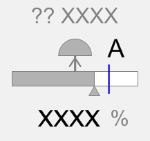
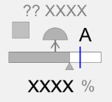
The tracker is a user-configured indicator that marks a specific output value on the OP bar. A typical use case is where an operator wants to mark the current position so that when they look at the position again (some time later) they can see if it has changed. The tracker position is set and enabled/disabled from the valve faceplate (see APG dashboard specification). The tracker is only available on valves with continuous position control (control valves, dampers, and complex MOV/EOVs).
Connects to: EquipmentName.CtrlMode, EquipmentName.CtrlModeDef
This is a single-character code that indicates the mode of the valve. It is shown next to the valve head. Typically, the set of modes includes Manual (M), Auto (A), Cascade (C) and Local (L) and special control (a computer symbol) but others may be added as required for the Control System platform.
Note: The Mode Indicator is not displayed if the tag is set to CtrlModeDef. To view the control mode at all times, remove the CtrlModeDef tag from the equipment template.
Where applicable, the valve stem is used to show the fail action for the valve (fail open, fail closed, or fail last). These states are shown as follows:

Connects to: EquipmentName.Open, EquipmentName.POS, EquipmentName.Closed, EquipmentName.Opening, EquipmentName.Closing
For control valves and dampers, the fill color of the valve head is used to indicate whether the valve is fully closed, partially open, or fully open. This is similar to the way fill color is used for the OP bar and readback indicators. When fully closed the fill is white. When partially open the fill is grey, and when fully open the fill turns black.
If readback is available the valve head fill should indicate the readback position. Otherwise it should indicate the commanded position.
|
State |
Control Valve |
Damper |
|---|---|---|
|
Fully closed |

|

|
|
Partially Open |

|

|
|
Fully open |

|

|
Connects to: EquipmentName.Open, EquipmentName.POS, EquipmentName.Closed, EquipmentName.Opening, EquipmentName.Closing
For MOV/EOVs and block valves, the valve head fill color follows the same scheme as for control valves and dampers.
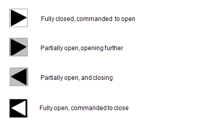
In addition to the position however, the valve heads for MOV/EOVs and block valves are also used to indicate transition states. That is, the valve head uses symbols from the Equipment Running State Indicator symbol set to show when the valve is opening or closing. Opening or closing is indicated with a triangle in the valve head. See examples below:

The special control indicator can be used to indicate either of two special states: field control and computer control. No symbol appears for valves that are under normal control via the SCADA system.
|
State |
Appearance |
|
|---|---|---|
|
Normal |

|
The valve is being controlled normally via the control system (no symbol shown) |
|
Handswitch control |

|
The handswitch control indicator appears when the valve is being controlled from the field via a local handswitch. |
Note: Check that the address configured for a valve in the PLC is the same as the tag address specified in Citect SCADA. If this is not configured correctly, the state and output value of the valve will not be accurate.
See also
Published June 2018