The Analog Controller faceplate can be associated with control meters such as a Flow meter.
The Analog Controller faceplate comprises the following components:
| Component | Description | Associated Tags |
|---|---|---|
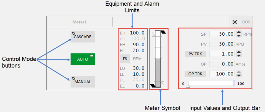
| Control Mode buttons |
Auto, Manual and Cascade buttons are displayed on this faceplate. The button is green when a mode is active. When the tag associated with the equipment is 0, the mode is Auto. When the tag is 1, the mode is Manual and when the tag is 2, the mode is Cascade. Clicking a mode button sends a command to the linked PLC. The Mode button displays two symbols:
|
|
| Equipment Limits |
The following limits are displayed on the left-hand side of the meter symbol:
If the values lie outside the practical values, additional indicators are displayed. The color of the equipment limits changes as the meter values change. If the practical range is the same as the engineering range, the practical range will be hidden. |
|
| Alarm Limits |
Displays the following alarm limits on the left-hand side of the meter symbol:
These are the standard analog alarm limits. If these alarm limits are not configured, they will not be displayed. Note: You can now configure custom digital alarm limits based on the PLC alarm limits. The FS (Full scale) button can be used to toggle the meter into full scale even when the PV is within the practical range. The units of measurement of the PV are displayed to the right of the FS button. |
Note: These tags are used if the UsePLCLimits parameter is "true" unless the PLCLimits parameter has been changed from the default. If the UsePLCLimits parameter is "false", values come from the alarm limit configuration of the PV tag. |
| Meter Symbol | Symbol for the currently selected meter. | |
| Faceplate Inputs |
Shown on the right-hand side of the meter symbol. Most of these are selected in the Composite Genie presentation options. These include:
Note: You can configure the Setpoint increment by using an Equipment Runtime Parameter on your equipment. This is not supported on the default faceplates, but you can modify the faceplate to achieve this. Specify a name for the parameter (for example, SPStep) on the Numeric Input Composite Genie of the faceplate. Also, the IsTag property needs to be set to FALSE. |
|
| Output Bar | Displayed below the input values. This shows the expected output along the bar and the actual output indicated by a triangle below the bar. The output indicator is visible only when the controller is in Auto or Cascade mode. It is not visible in Manual mode. |
Published June 2018