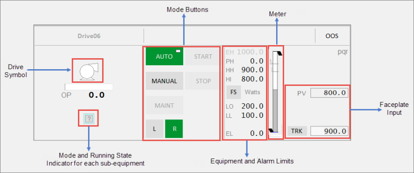
This faceplate is used for single and multiple Variable Speed Drive (VSD) control. It is used for variable drives and groups of variable speed drives. This faceplate functions similar to the multiple DOL drive faceplate. The Equipment Running State Indicators are positioned like the multiple DOL drive faceplate based upon the number of drives.
| Component | Description | Associated Tags |
|---|---|---|
| Drive Symbol |
Symbol for the drive associated with the selected equipment. Clicking on the multiple equipment object selects that particular drive. The buttons, meter and readings are then populated for that drive. |
|
| Output Bar | This shows the expected output along the bar. | |
| Mode Indicators for each related equipment |
Running State Indicators and control modes for each related equipment displayed below the drive symbol. The last two characters of the tagname for each drive are shown over each multiple equipment indicator to distinguish between the drives. Note: If the drive does not have any MEOs, a Running State Indicator and control mode will be displayed for the drive itself in the center position. The last two characters' label and the label above the drive are not shown. The mode indicator is not selectable. Indicators for up to 5 VS drives can be displayed here. |
|
| Mode buttons |
Mode buttons are green when a mode is active, and grey when inactive. When the CtrlMode tag associated with the equipment is 0, the mode is Auto. When the tag is 1, the mode is Manual. This tag applies to Auto and Manual buttons. The Mode button displays two symbols:
The following mode buttons are displayed: |
|
|
|
|
|
|
|
|
|
|
|
|
|
|
|
|
|
||
| Equipment Limits |
The following limits are displayed on the right-hand side:
If the values lie outside the practical values, additional indicators are displayed. The color of the equipment limits changes as the meter values change. If the practical range is the same as the engineering range, the practical range will be hidden. |
|
| Alarm Limits |
Displays the following alarm limits on the right-hand side:
These are the standard analog alarm limits. If these alarm limits are not configured, they will not be displayed. Note: You can now configure custom digital alarm limits based on the PLC alarm limits. The FS (Full scale) button can be used to toggle the meter into full scale even when the PV is within the practical range. The units of measurement of the PV are displayed to the right of the FS button. |
Note: These tags are used if the UsePLCLimits parameter is "true" unless the PLCLimits parameter has been changed from the default. If the UsePLCLimits parameter is "false", values come from the alarm limit configuration of the PV tag. |
| Meter | Meter displayed for the PV of the equipment. |
Published June 2018