The drive objects that are available in the Situational Awareness library are classified into the following groups:
They are all similar in their elements and functionality. The equipment symbol (see below) is the only element that is unique to each drive type.
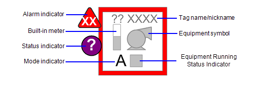
The image below shows the elements that make up a basic drive object.

Note: The drive object includes a built-in meter so that you can display a key analog value next to the drive symbol. If you do not want the side meter, you do not need the following item: PV.
If you want your drive to have multiple analog values, you can display those as separate meter objects using meter composite genies. When using meters the addresses and tag names need to be unique. Use a prefix on the item name. For more information refer to Meters.
Connects to: Running, Stopped
The equipment symbol indicates the following:
A dark fill indicates the run status of a drive is 'on' or 'running'. A white fill indicates the drive is 'off' or 'stopped'.

Some equipment symbols are available in variations that point in a particular direction.
An alarm indicator is used to show the occurrence and status of alarms associated with an object. See Use Alarm Indicators for more information.
Connects to: EqStatus.
A running state indicator is used to represent various non-alarm conditions associated with an object, such as abnormal data quality or control system states. See Status Indicators in the section on Common Object Properties.
Connects to: RunStatus.
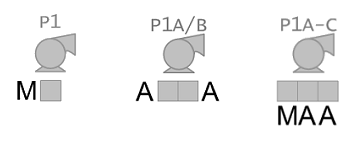
An Equipment Running State Indicator is a compact indicator that can be used to represent a variety of states for drive objects They allow an object to represent a group of drives. See Equipment Running State Indicators in the section on Common Object Properties.
Connects to: PV.
This item is available to accommodate drive objects that have an integrated meter for motor amps or kilowatts. It is built using a small version of the meter symbol and graphical PV from the Miscellaneous meter. To give the graphics designer flexibility to put the relevant information next to the object, the item name that drives this graph has been given a name that describes its use on the genie.
The built-in meter element is only shown if the reading is available. It is only available for single-drive objects, it is not used with groups of multiple drive objects.
For drive objects with a left-facing option, the built-in meter is moved to the right-hand side of the equipment symbol.

The tag name/nickname field shows the equipment tag name (by default), or, if entered by the user, a “nickname”. The nickname is usually a common name used to help identify the reading (for example, “Oil pump”, instead of “P4509”).
Connects to: CtrlMode, CtrlModeDef
This is a single-character code that indicates the current mode of the drive.

Control Mode Indicator states:
Note: The Mode Indicator is not displayed if the tag is set to CtrlModeDef. To view the control mode at all times, remove the CtrlModeDef tag from the equipment template.
The AutoCmd, ManCmd, CasCmd, FwdCmd, LocalCmd, MaintCmd, RemCmd, RevCmd, StartCmd, StopCmd, OOSCmd tags work in conjunction with the CtrlMode tag. For more information, see Create a New Faceplate.
If a drive object includes Equipment Running State Indicators, the following positioning is used:

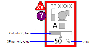
If the object represents a variable speed drive (VSD), it may also include the following additional elements.

Connects to: OP.
The output (OP) bar provides a graphical representation of the commanded output for a variable speed drive (VSD). See Output (OP) Bar in the section on Common Object Properties.
When dealing with a group of 2 or more drives, the VSD output bar should only be shown if there is only one VSD in the group, or if there is a common controller for all of the drives in the group. If the group includes two or more separate VSDs, either the VSD output indicator should not be shown, or two separate drive objects should be used.
The readback indicator is only shown for drives where readback is available. Generally this will show the actual speed of the drive, measured as a percentage. When a group of drives with a VSD is shown, and readback is available, readback indicators are shown for each drive.
Connects to: OP.
For variable speed drives, a numeric representation of the OP can provide operators with precise values when needed. This is measured as a percentage value.
The visibility of the numeric OP is tied to the visibility state for PVs (as specified in the Show/Hide Settings). If the user selects to turn off the visibility for PVs, the numeric OP values is also hidden.
Represents the unit of measurement for the output. Typically, this will be percentage (%) for VSD output.
See Also
Published June 2018