- OP
- ORHigh, ORLow, ORDsp
- PRHigh, PRLow
- OPTrack, PVTrack, TrackDsp
- PV
- SP
- CtrlMode, CtrlModeDef
- AutoCmd, ManCmd, CasCmd
- RunStatus
- OOS, OOSDisabled
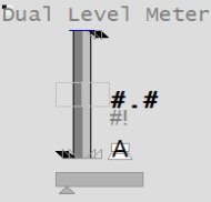
This object provides a compact way to monitor two related levels simultaneously. The level indication is presented on a linear scale. For example, you could use a Dual Level meter to indicate the levels of two tanks. One of the tanks is shown in a slightly darker shade of gray than the other. The Dual Level meter is designed to display the values of two levels that share a common set of scales (engineering range, practical range and alarm limits).
Note: If you need to display the values of two levels with different scales, use the Multiple Meter.
| Property | Description |
|---|---|
| Name | Dual Level |
| Graphical Representation |

|
| Example Equipment Template | Meter |
| Associated Composite Genie | Meter.xml |
| Equipment.Items that the Genie expects | |
| Associated Faceplate(s) | |
| Equipment.Items that the Faceplate Expects |
|
The following presentation options are available for this object.
|
Option |
Description |
|---|---|
|
Meter Type |
From the dropdown list, select Dual Level. |
|
Reference Equipment Name |
Enter the full name and path for the equipment associated with the dual meter. The path and name should be prefixed with the equipment's cluster name for multi-cluster systems. You can enter a maximum of 160 characters for this option. |
|
Equipment Name and Equipment #2 Name |
Enter the full name and path of the two equipment objects. You can enter a maximum of 160 characters for this option. |
| Equipment Item Prefix and Equipment #2 Item Prefix |
Prefix applied to the equipment item name. This allows for displaying multiple values for a single piece of equipment. For example, you want to create two meters to monitor power or voltage for a single pump. You would create two meters on the pump and assign the equipment item prefix "Power1" and "Power2" or "Voltage1" and "Voltage2". So, the PV values for the meters would be Power1PV, Power2PV, etc, respectively. Note: To get a meter with a prefix to work correctly, you need to create tags with the required item names. From the example above, you will need to create the tags Power1PV, Power2PV and so on. The following equipment item names can be prefixed:
|
|
Size |
Size of the meter object image - small or large |
|
Orientation |
Select the orientation that is appropriate for the presentation of the object on the graphics page. |
|
Display Label |
Use this setting to display a label at the selected position. Select None if you do not want to display a label. |
|
Label |
Enter the text that will display at the location specified in Display Label field. You can enter a maximum of 30 characters for this option. |
|
Display Status Indicator |
Select the location to display a status indicator. Select None if you do not wish to see the status indicator. For more information, see Status Indicators. |
|
Display Process Variable |
Select to display a process variable (numeric PV) with the meter. This option is selected by default. |
|
Display Control Mode |
Select this option to display the Controller Mode Indicator. On selecting this option the “Display Control Readback” option box is also displayed. The Display Control Readback Indicator represents the actual output for the controller. |
|
Display Controller Output |
Select to display an output indicator with the meter. For more information, see Output Bar. |
|
Display Setpoint |
Select to display a setpoint indicator with the meter. |
| Display OOS | Select to display Out of Service indicator. |
|
Display Control Readback |
Select to display a readback indicator (also known as feedback indicator) with the meter. |
|
Mirrored |
Inserts a mirror image of the meter based on the selected presentation options. |
Note: The Control Mode, PV and OP bar take values only from Equipment Name. Equipment Name #2 is only used to display the height of the second bar (the light grey bar).
See Also
Published June 2018